 English
 Español
A small fault occurs on a motor branch circuit deep inside a manufacturing plant. The 100A feeder breaker trips instead of the 16A branch breaker—and the entire production line shuts down. Maintenance spends hours tracing the problem, resetting the main breaker, and restarting equipment. The root cause? A lack of selective coordination in the protection design.
Designing reliable circuit protection for industrial power distribution is not simply about selecting breakers with adequate current ratings. It is about building a coordinated system where the right device trips at the right time, isolating faults locally while keeping the rest of the facility running.
This guide covers the core principles of industrial protection design, the role of different breaker types, and the practical steps for achieving selective coordination.
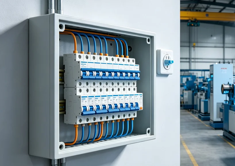
Understanding the Anatomy of an Industrial Power Distribution System
Before designing protection, it helps to understand how industrial power distribution is structured.
The Feeder and Branch Circuit Model
Industrial power systems typically follow a hierarchical structure:
-
Main switchboard — receives power from the utility or on-site generation
-
Feeders — distribute power from the main switchboard to sub-panels or load centers
-
Branch circuits — supply individual loads such as motors, welding machines, lighting, and control panels
Each level of this hierarchy requires appropriate protection. The design objective is that a fault on a branch circuit should only trip the branch breaker—not the feeder breaker or the main breaker. This is the essence of selective coordination.
Key Protection Devices in Industrial Systems
Industrial power distribution relies on several types of protection devices:
| Device Type | Primary Function | Key Characteristics |
|---|---|---|
| MCBs (Miniature Circuit Breakers) | Overcurrent protection for branch circuits | 0.5–125A, fixed trip curves (B/C/D), up to 10–15kA breaking capacity |
| MCCBs (Molded Case Circuit Breakers) | Main and feeder protection | 15A–2500A+, adjustable trip settings, up to 200kA breaking capacity |
| RCCBs (Residual Current Circuit Breakers) | Earth leakage protection | 16–100A, 10/30/100mA sensitivity, does not provide overcurrent protection |
| Protection Relays | Fault detection and decision-making | Monitor current, voltage, frequency; send trip signals to circuit breakers |
Protection relays act as the “brain” of the system, detecting abnormal conditions, while circuit breakers serve as the “muscle,” physically interrupting current. In modern industrial systems, these two functions are often combined in electronic trip units within MCCBs.
The Foundation of Reliable Protection — Selective Coordination
What Is Selective Coordination?
Selective coordination (also called discrimination or selectivity) ensures that when a fault occurs, only the protection device immediately upstream of the fault opens. All upstream devices remain closed, and all other circuits continue operating.
Why Coordination Matters
| Benefit | Explanation |
|---|---|
| Minimizes downtime | Only the affected circuit is disconnected; production continues elsewhere |
| Protects equipment | Faults are cleared quickly and at the correct location, reducing thermal and mechanical stress on equipment |
| Improves safety | Reduces arc flash risk and ensures faster fault clearing for maintenance personnel |
| Reduces costs | Prevents unnecessary replacement costs and financial losses from extended outages |
How Coordination Is Achieved
Coordination relies on three core principles:
1. Current Selectivity — Downstream devices trip at lower current levels than upstream devices. This ensures that smaller faults are cleared locally.
2. Time Selectivity — Downstream devices operate faster, while upstream devices have intentional delays. This creates a time-based coordination hierarchy.
3. Energy Selectivity — Some circuit breakers are designed to limit let-through energy during a fault, reducing stress on downstream components. This capability depends on manufacturer-provided selectivity tables and verified performance under specific short-circuit conditions.
The Coordination Study
A protection coordination study is the formal process of verifying that protective devices are properly coordinated. The study involves:
-
Collecting system data (load flow, short-circuit current calculations)
-
Plotting time-current curves (TCCs) for each device
-
Setting coordination intervals so downstream devices operate before upstream devices
-
Verifying that settings achieve selectivity without compromising protection
For complex industrial systems with multiple distribution levels, this study is essential—not optional.
Selecting the Right Breaker for Each Level
Main and Feeder Protection
For main incoming and feeder positions, MCCBs are typically required due to their higher current ratings and adjustable trip settings. The HM series moulded case circuit breaker offers rated currents from 10A to 630A with insulation voltage up to 800V and impulse withstand voltage of 8kV, compliant with IEC 60947-1/2.
Key considerations for main/feeder MCCBs:
-
Breaking capacity (Icu) must exceed available fault current
-
Electronic trip units enable adjustable settings for coordination
-
Ics = 100% Icu means the breaker can be reused after a fault
Branch Circuit Protection
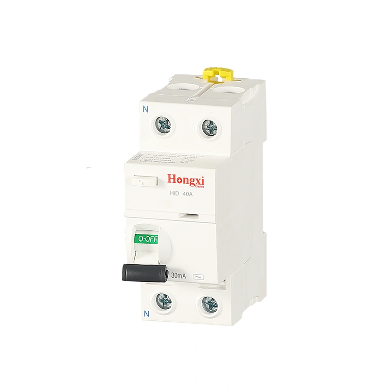
For branch circuits serving individual loads, MCBs are the standard choice. For the HX2 and HX5 series, the 10kA breaking capacity makes them suitable for industrial control panels and branch protection. MCBs provide quick response, resettable operation, and manual tripping capability. RCCBs (such as the HID series) provide dedicated earth leakage protection and must be paired with upstream MCBs or MCCBs for overcurrent protection. This combination makes them suitable for residential, commercial, and industrial circuits where ground fault protection is required.
Motor Circuit Protection
For motor branch circuits, dedicated motor protection circuit breakers are recommended. The HGV2 series offers adjustable current ranges from 0.1A to 63A with phase failure protection and overload protection. MPCBs provide:
-
Adjustable thermal trip settings matched exactly to motor FLA
-
Phase failure detection to prevent motor burnout
-
Compact design integrating overload and short-circuit protection
The Governing Standards for Industrial Protection Devices
For industrial power distribution, the primary standard for circuit-breakers (such as MCCBs and MCBs) is the IEC 60947 series. The latest version, IEC 60947-2:2024 (Edition 6.0), published in September 2024, applies to breakers with rated voltages up to 1,000V AC or 1,500V DC. It introduces important technical changes, including new requirements for ground-fault testing, EMC, and the use of DC voltage for dielectric tests.
However, it is critical to distinguish this from the standard for residual current circuit-breakers without overcurrent protection (RCCBs). For devices like the HID series RCCB, which are widely used for ground fault protection, the applicable standard is IEC 61008-1. This standard governs their performance, including the 6kA rated conditional short-circuit current and the ≤0.1s residual current breaking time. Therefore, when designing protection, select the standard based on the specific device type: IEC 60947-2 for main circuit-breakers and IEC 61008-1 for RCCBs.
5 Steps to Design Reliable Industrial Circuit Protection
Step 1: Map the Distribution Architecture
Draw a one-line diagram showing all distribution levels: main switchboard → feeders → sub-panels → branch circuits. Label each level with:
-
Expected load current
-
Available fault current
-
Cable sizes and lengths
Step 2: Perform Short-Circuit Calculations
Calculate the prospective short-circuit current at each point in the system. This determines the required breaking capacity (Icu) for each protection device. For industrial systems, fault currents can exceed 25kA at main panels, requiring MCCBs with adequate interrupting capacity.
Step 3: Select Devices by Level
-
Main and feeders: MCCBs with electronic trip units for adjustable settings
-
Branch circuits: MCBs or MPCBs matched to load type
-
Motor circuits: MPCBs with adjustable thermal trips
-
Earth leakage: RCCBs for personal protection (30mA) or equipment protection (100mA)
Step 4: Plot Time-Current Curves and Verify Coordination
Obtain manufacturer time-current curves for all devices. Verify that curves do not overlap in ways that would cause upstream devices to trip before downstream devices. Adjust settings (where available) to achieve coordination intervals.
Step 5: Apply Temperature Derating
For installations in hot environments, apply manufacturer derating factors. At 50°C ambient, current-carrying capacity may be reduced by 8–10%. Select devices with appropriate margin.
For applications requiring selective coordination and adjustable protection settings in complex industrial networks, explore moulded case circuit breaker options with electronic trip units.
Real-World Application Example — Automotive Parts Factory
Consider a factory with:
-
Main incoming: 630A, 25kA fault current at 415V
-
Feeders: Six 100A feeders serving production areas
-
Branch circuits: Motor circuits (5–15kW), lighting, control panels, welding equipment
Protection design:
-
Main: 630A MCCB with electronic trip unit (50kA Icu), adjustable short-time delay for coordination
-
Feeders: 100A MCCBs with thermal-magnetic trip units, set for current selectivity
-
Motor branches: HGV2 MPCBs set to each motor’s FLA, paired with HC2 contactors
-
Control circuits: HX series MCBs with C-curve for PLC and sensor protection
-
Surge protection: HS Type 2 SPDs at main and sub-panels
Coordination verification: Time-current curves show the 16A branch MCB trips before the 100A feeder MCCB for all fault currents up to the branch breaker’s breaking capacity.
Next Steps — From Design Principles to Component Specification
You now have a practical framework for designing reliable circuit protection for industrial power distribution. The key takeaways are:
-
Selective coordination is the foundation of reliable protection — it ensures faults are isolated locally
-
Protection devices must be matched to distribution level — MCBs for branches, MCCBs for feeders and mains
-
The coordination study is essential for verifying that devices operate correctly together
-
IEC 60947-2:2024 sets the latest requirements for industrial circuit breakers, while IEC 61008-1 governs RCCBs like the HID series
-
Temperature derating and environmental factors must be considered in the design
Once you have mapped your distribution architecture and identified the protection requirements for each level, comparing the specific technical specifications of available devices becomes the logical next step.
After establishing your industrial power distribution protection requirements — distribution levels, fault currents, and coordination needs — you can review the technical specifications of HM series MCCB for main and feeder applications, or explore MCB options for branch circuit protection.
Related Reading
-
How to Select an MCCB Manufacturer for Industrial Projects
-
Electrical Protection Challenges in Factory Automation Systems