A solar inverter fails after a thunderstorm passes through the area. The homeowner assumes lightning struck the array directly. In reality, the strike may have been miles away—but the electromagnetic field induced a surge voltage that traveled through the DC cables and destroyed the inverter’s sensitive electronics.
Photovoltaic systems are uniquely vulnerable to surge damage due to their exposed location, long DC cable runs, and sensitive semiconductor components. Yet many solar installations still lack adequate surge protection.
This guide explains why surge protective devices (SPDs) are essential for PV systems, how to select the right type for each installation point, and how to deploy them effectively on both the DC and AC sides.
Why PV Systems Are Uniquely Vulnerable to Surge Damage
PV systems combine three characteristics that make them exceptionally susceptible to transient overvoltage damage:
-
Exposed positioning: Arrays are mounted on rooftops or open fields—the highest points on a property, naturally attracting or intercepting lightning activity
-
Long DC cable runs: Cables from the array to the inverter can extend tens or hundreds of meters, acting as efficient antennas for induced surges
-
Sensitive electronics: Inverters and charge controllers contain components that can fail after only a few overvoltage pulses
Laboratory evidence from a study presented at the 37th International Conference on Lightning Protection (ICLP 2024) found that inverters using only internal protection failed after just 1 to 7 simulated lightning impulses. However, when protected by external SPDs on both the DC and AC sides, the same inverters withstood 100 applied surges without damage.
Surges can invade a PV system through two pathways: on the DC side from lightning induction, and on the AC side from grid switching events. Without SPDs on both sides, the system remains exposed.
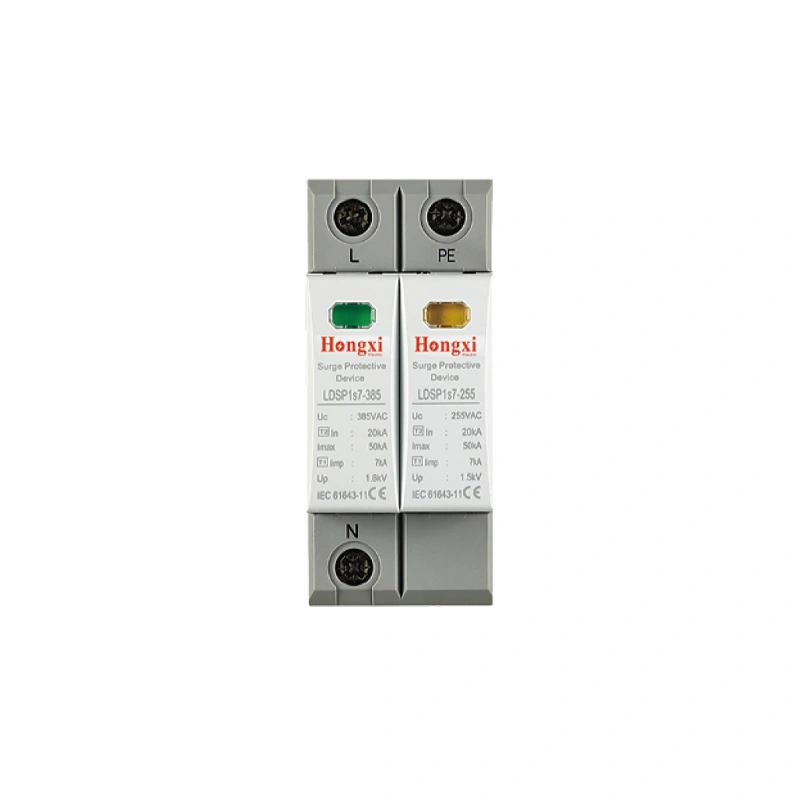
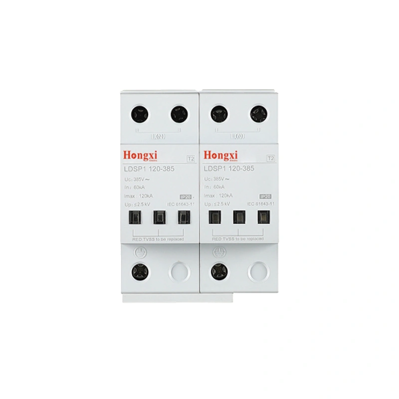
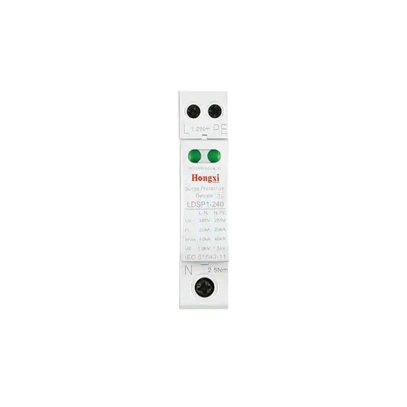
For detailed specifications of surge protective devices for various applications, review the HS series surge protective device family including AC Type 1+2 and Type 2 units.
Understanding SPD Types for PV Systems
The International Electrotechnical Commission (IEC) classifies SPDs into three types under the IEC 61643 series. Each type is defined by its test waveform and intended installation location:
| SPD Type | Test Waveform | Application in PV Systems |
|---|---|---|
| Type 1 (Class I) | 10/350μs (simulates direct lightning strike) | Service entrance where an external lightning protection system (LPS) exists |
| Type 2 (Class II) | 8/20μs (simulates induced surges) | DC combiner boxes, inverter DC input, AC distribution panels — most common for residential solar |
| Type 3 (Class III) | 1.2/50μs + 8/20μs (residual surges) | Terminals of sensitive equipment must be coordinated with upstream SPDs |
For photovoltaic applications, Type 2 SPDs are the most widely used. They are installed on the equipment side to protect against surge currents conducted or induced through cables. Combined Type 1+2 SPDs are also available for systems where separation distance from an external lightning protection system cannot be maintained.
IEC 61643-31: The Dedicated PV Standard
The governing international standard for surge protection in photovoltaic installations is IEC 61643-31:2018 — Low-voltage surge protective devices — Part 31: Requirements and test methods for SPDs for photovoltaic installations. This standard specifies requirements for SPDs connected to the DC side of PV installations rated up to 1,500 V DC. SPDs complying with this standard are exclusively dedicated to installation on the DC side of photovoltaic generators and inverters.
The Chinese national equivalent, GB/T 18802.31-2021, has been in effect since October 1, 2021, aligning with the international standard.
For applications requiring coordinated voltage monitoring alongside surge protection, adjustable voltage and current protectors offer real-time over/under voltage protection for sensitive PV and industrial equipment.
Key Selection Parameters for PV SPDs
Selecting the right SPD for a PV system requires evaluating several critical parameters.
Maximum Continuous Operating Voltage (Uc / MCOV)
Uc is the maximum voltage that can be continuously applied to the SPD without degradation. For the DC side, Uc must exceed the system’s maximum open-circuit voltage (Voc) after temperature correction. Industry guidance recommends adding at least a 10% safety margin above the worst-case Voc:
-
600 V DC system → select SPD with Uc ≥ 660–700 V DC
-
1000 V DC system → select SPD with Uc ≥ 1000–1200 V DC
-
1500 V DC system → select SPD with Uc ≥ 1500–1800 V DC
If Uc is too low, the SPD will continuously conduct current and fail quickly. If Uc is too high, the voltage protection level (Up) increases, potentially allowing damaging residual voltage to reach equipment.
Nominal Discharge Current (In) and Maximum Discharge Current (Imax)
In represents the surge current the SPD can withstand multiple times (typically 15 surges). IMAX represents the single-pulse withstand capacity.
| Application | Recommended In | Recommended Imax |
|---|---|---|
| Low lightning density | ≥10 kA | ≥20 kA |
| Moderate risk / residential | ≥20 kA | ≥40 kA |
| High lightning activity | ≥20–40 kA | ≥60–80 kA |
Voltage Protection Level (Up)
Up is the residual voltage that appears across the SPD’s terminals during a surge. This voltage is what the protected equipment actually experiences. Up must be lower than the impulse withstand voltage of the downstream equipment — typically below 2.5–4 kV for PV inverters.
The “<10 Meter Rule.”
A widely accepted industry guideline states: if the distance between the PV array and the inverter is less than 10 meters, a single SPD installed near the inverter suffices. If the distance exceeds 10 meters, SPDs should be installed at both ends — one near the array and one near the inverter. This recommendation is documented in Furse’s application note AN014 (Protection of Photovoltaic Systems).
Placement Strategy — Where to Install SPDs in PV Systems
A properly protected PV system requires SPDs at multiple locations.
DC Side (Generator to Inverter)
-
DC combiner box: Install DC-rated Type 2 SPDs at each combiner box input, matched to string voltage
-
Inverter DC input: Install DC-rated SPDs at the inverter’s DC input terminals — the final defense before surge energy enters the inverter
-
Long cable runs (>10m): Add SPDs at both the array end and the inverter end
AC Side (Inverter to Grid)
-
Inverter AC output: Install AC-rated Type 2 SPDs to protect against grid-side surges propagating back toward the inverter
-
AC distribution panel: Install AC-rated SPDs at the main panel where the PV system connects to the grid
Special Cases
-
Systems with external lightning protection (LPS): Type 1 or combined Type 1+2 SPDs are required at the building entry point
-
Ground-mounted large-scale PV plants: Consider external lightning rods and equipotential bonding in addition to SPDs
Installation Best Practices
Proper installation directly affects SPD performance:
-
Keep connection leads short: Leads should be under 0.5 meters, never exceeding 1 meter — longer leads create inductive voltage drop that raises effective protection level
-
Use adequate conductor sizing: Minimum 6 mm² copper for Type 2 SPDs (16 mm² for Type 1)
-
Verify grounding quality: Ground resistance should be less than 4Ω for independent grounding, less than 1Ω for integrated grounding
-
Install backup overcurrent protection: Use DC-rated fuse or breaker upstream of each SPD. Never use an AC-rated breaker for DC circuits
-
De-energize and cover PV modules before working: PV modules generate hazardous voltage whenever light is present
Regular Inspection
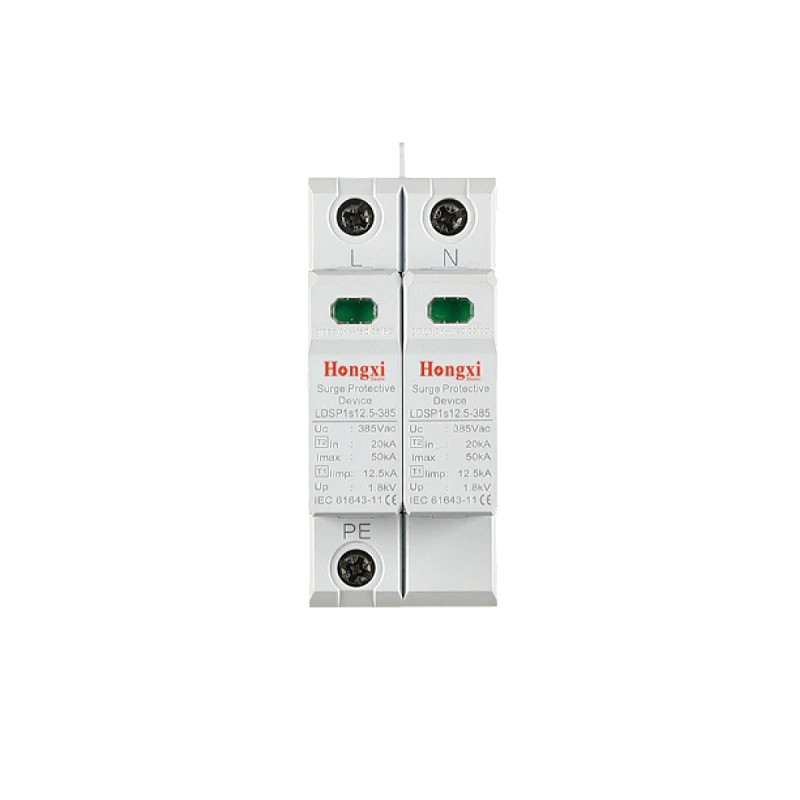
Most SPDs include a mechanical status indicator — green for functional, red for failed. Failed SPDs offer no protection. Inspection frequency: residential systems every 6 months; commercial systems monthly; critical infrastructure weekly.
A Practical Selection Walkthrough
Consider a rooftop commercial PV system with:
-
1000 V DC nominal, Voc (cold) ~1200 V DC
-
DC cable length: 25 meters (exceeds 10m)
-
High lightning region (50+ thunderstorm days/year)
-
No external LPS
-
Inverter withstand voltage ≤3.5 kV
Selection decisions:
-
SPD type: Type 2 DC SPD (Type 1+2 optional for margin)
-
Uc: 1200 V × 1.15 = minimum 1380 V DC → select Uc ≥1500 V DC
-
In/Imax: ≥20 kA / ≥40 kA (prefer 80 kA)
-
Up: ≤2.5 kV (below inverter’s 3.5 kV withstand)
-
Placement: SPD at combiner box + SPD at inverter DC input
-
AC side: Type 2 AC SPD at inverter AC output and main panel
Next Steps — From Selection Principles to Component Specification
You now have a practical framework for specifying SPDs in PV systems. Key takeaways:
-
PV systems need protection on both DC and AC sides
-
Match UC to system Voc with ≥10% margin
-
Select In/Imax based on lightning exposure
-
Follow the “10-meter rule” for placement
-
Installation quality determines real-world performance
Once you have determined your PV system’s voltage level, lightning exposure, and equipment sensitivity, comparing specific technical data becomes the logical next step.
After establishing your PV system’s surge protection requirements, you can review the technical specifications of HS series surge protective device— including Type 2 DC-rated models, combined Type 1+2 units, and AC-side protectors with appropriate Uc and Up ratings.
Related Reading
-
Contactor vs MCB for Motor Control Applications
-
Reduce Replacement Frequency with High-Endurance MCB
-
SPD Coordination and Cascading Protection for Low-Voltage Systems