 English
 Español
When an industrial control panel trips unexpectedly on the factory floor, the immediate cost is measured in downtime—minutes of lost production, hours of troubleshooting, and potentially damaged equipment. Yet many panel builders and maintenance engineers rely on the same miniature circuit breaker (MCB) specifications used for lighting circuits, without realizing that motor inrush currents, control transformer surges, and short-circuit coordination requirements demand a different approach.
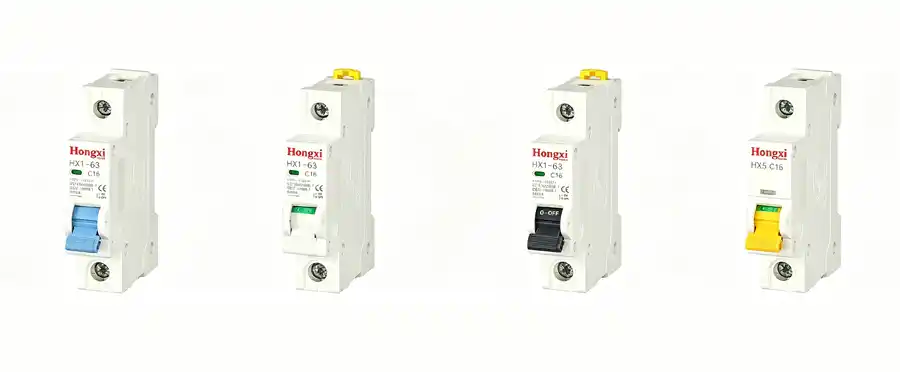
This guide walks you through the three most critical MCB selection parameters for industrial control applications: breaking capacity, trip curve characteristics, and selective coordination with downstream devices. By the end, you will have a practical framework for specifying MCBs that protect without nuisance tripping.
Breaking Capacity – Matching the MCB to Your Panel’s Fault Current
The breaking capacity of an MCB is the maximum fault current it can safely interrupt without welding its contacts or exploding. In industrial control panels located near a service transformer, available short-circuit current can reach 10kA or more. If your MCB is rated for only 6kA, a downstream fault could destroy the breaker before it opens.
Why does this matter for your panel? A breaker that interrupts a fault beyond its rating may fail catastrophically, sending ionized gas and debris across adjacent components. For control panels containing PLCs, relays, and HMI screens, such an event often means replacing the entire enclosure.
According to a 2021 technical paper from the National Fire Protection Association (NFPA), a significant percentage of electrical equipment failures in industrial settings trace back to improperly specified overcurrent protective devices relative to available fault current.
Practical guidance for control panels:
-
Panels fed directly from a 500kVA or larger transformer often see 10kA–22kA fault current at the main terminals
-
Panels located far from the transformer (long cable runs) may have fault current reduced to 3kA–6kA
-
Always calculate or measure available fault current at the panel input; never guess
For main incoming MCBs in an industrial control panel, a breaking capacity of 10kA (consistent with HX2 or HX5 series specifications) provides a safe baseline for most factory environments. Branch circuits feeding individual motors or solenoids may tolerate lower ratings, but maintaining uniform 10kA throughout simplifies spare parts management.
For a deeper look at how breaking capacity interacts with other protective elements in a complete panel design, review the technical overview of miniature circuit breaker families designed for industrial environments.
Trip Curves – Why B-Curve is Rarely Correct for Control Circuits
Trip curves (B, C, D, and F) define how quickly an MCB responds to overload and short-circuit conditions. The letter indicates the multiple of rated current (In) at which the magnetic trip (instantaneous) element activates.
| Curve Type | Magnetic Trip Range (Multiple of In) | Typical Applications |
|---|---|---|
| B-curve | 3–5× In | Resistive loads (heating, lighting), long cable runs |
| C-curve | 5–10× In | Small motors, solenoids, control transformers, and general industrial |
| D-curve | 10–20× In | Large motors, welding equipment, high-inrush loads |
| F-curve | 6–9× In (optimized) | Transformer-coupled loads, specific control circuits |
The most common mistake in control panels: selecting B-curve MCBs because they appear “more sensitive” to overloads. In reality, an industrial control panel contains multiple inductive loads. When a 24V DC power supply or a small contactor coil energizes, it draws an inrush current 8–15 times its steady-state value for a few milliseconds. A B-curve breaker (tripping at 3–5× In) may see this inrush as a fault and open—a classic nuisance trip.
Industry guidance from the International Electrotechnical Commission (IEC 60947-2) clarifies that circuit breakers for motor control and transformer-fed circuits should be selected based on measured or calculated inrush duration.
Selection rule for control panels:
-
C-curve (5–10× In) is the correct default for nearly all branch circuits in industrial control panels—motor starters, relay coils, solenoid valves, and power supplies
-
D-curve only when individual branch motors exceed 1kW or when a manufacturer explicitly requires it
-
Avoid B-curve except for purely resistive loads or circuits with very low inrush
For panels mixing multiple load types, understanding how different protection devices coordinate with the motor protection circuit breaker can prevent a small branch fault from taking down an entire production line.
5 Steps to Specify MCBs for a New or Retrofit Control Panel
Use this decision sequence when building or upgrading an industrial control panel. Each step answers one specific question.
Step 1: Determine the panel’s available short-circuit current at the incoming terminals.
Calculate using transformer kVA, impedance percentage, and conductor length. If uncertain, assume 10kA for general industrial environments and 22kA for locations within 10 cable meters of a 1MVA transformer.
Step 2: Select the main incoming MCB breaking capacity.
Choose a rating equal to or greater than the calculated fault current. For most panels, 10kA provides adequate protection with reasonable cost. For high-fault locations, consider 15kA or 25kA-rated devices.
Step 3: Assign trip curves by branch circuit type.
-
Lighting, heaters, and purely resistive loads → C-curve (or B-curve only after verifying zero inductive load)
-
Control transformers, power supplies, contactor coils, solenoid valves → C-curve standard
-
Individual motor branch circuits >0.5kW → C-curve or D-curve as recommended by motor starter manufacturer
Step 4: Verify selective coordination for critical circuits.
For a production line where stopping one machine should not halt the entire panel, ensure the branch MCB trips before the main MCB. This requires the main MCB to have a higher short-circuit trip threshold or a slight delay. Full selectivity often requires comparing time-current curves from the manufacturer.
Step 5: Check physical fit and terminal compatibility.
Industrial control panels typically use 35mm DIN rail mounting. Each MCB pole occupies 18mm width. Verify that your selected MCB family (1P, 2P, 3P, or 4P as needed) fits within the allocated panel space and accepts the conductor sizes (stranded or solid copper) used in your wiring schedule.

Real-World Example – Motor Control Panel with Mixed Loads
Consider a small motor control panel feeding three 0.75kW pumps (each with a contactor starter), one 1.5kW ventilation fan, a 24V DC power supply for sensors, and panel lighting.
-
Pump and fan branches: Each motor draws 6–12A running current but experiences 8× inrush at start. C-curve MCB rated at 1.5× motor FLA prevents nuisance tripping during starting while providing overload protection.
-
24V DC power supply: This switching power supply draws a high inrush current (often 20–30× steady-state for one-half cycle). A C-curve MCB sized at 1.25× the supply’s rated input current handles the inrush without tripping.
-
Panel lighting: Resistive load, but using the same C-curve MCB across all branches simplifies spare parts.
The selection principle is consistency: one trip curve family (C-curve) used throughout, with breaking capacity matched to the panel’s fault level rather than varied by branch.
Next Steps – From Selection Criteria to Component Specification
By now you have established three key decisions for your industrial control panel: the minimum breaking capacity required, the appropriate trip curve for each branch, and the coordination approach between main and branch MCBs. These decisions form the technical foundation of a reliable protection scheme.
The next logical step is comparing specific technical data sheets for MCB families that meet your chosen criteria—particularly verifying that the published time-current curves support your selective coordination requirements and that physical dimensions match your DIN rail layout.
Once you have clarified these key decision factors (breaking capacity, trip curve, and coordination needs), comparing the detailed specifications of available MCB families becomes the next logical step. You can review the technical parameters of HX series MCBs for industrial control applications—including their breaking capacity ratings, available trip curves, and physical dimensions.
Related Reading
-
DIN Rail Mounting Standards: What Panel Builders Need to Know
-
Motor Protection Circuit Breakers vs. MCB + Overload Relay
-
Overcurrent Protection for Control Transformers
-
Short-Circuit Current Rating (SCCR) for Industrial Control Panels