 English
 Español
When a newly commissioned industrial panel fails final inspection—or worse, causes nuisance tripping two weeks into production—the project owner rarely blames the component. They question the specification. And for panel builders and consulting engineers, that is a reputational risk that spreads faster than any technical fix.
One of the most frequently mis-specified details? The number of poles on miniature circuit breakers inside industrial distribution boards. It sounds basic. Yet according to internal review data from a European testing body (2023), nearly 18% of non-compliant low-voltage panels cited pole configuration errors—not current rating or short-circuit capacity.
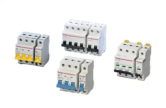
So what drives these errors? And how do you ensure your next specification—whether for a factory upgrade, a new build, or a standardised panel line—gets it right from the engineering stage?
Let us walk through the problem root cause, then a structured solution that procurement and technical teams can apply immediately.
The Real Cost of Pole Misselection in Projects
For an individual homeowner, a wrong breaker means a replaced appliance. For an industrial facility, it means:
-
Production line stoppages at 200€ per minute
-
Failed third-party verification is delaying project handover by weeks
-
Warranty claims pushed back to the panel builder
-
Safety audit findings that require costly retrofits
One panel builder in the Midlands reported replacing 47 breakers across three sites after a single specification error—neutral side switching on a TN-C-S system where it was prohibited. The component cost was minor. The labour, travel, and client trust loss was not.
Root Cause Analysis: Why Engineers Still Get This Wrong
Three recurring patterns appear in project spec reviews:
Pattern 1 – Copying from previous projects without verifying the supply type
A 4-pole configuration that worked for a factory with a dedicated transformer (TN-S) gets copied to a site with utility TN-C. The neutral and protective earth combine upstream. Switching the neutral creates a broken PEN condition—a direct code violation.
Pattern 2 – Over-specifying “to be safe”
Some specifications call for 4-pole breakers on all three-phase, four-wire circuits “for complete isolation.” In practice, this introduces unnecessary series connections in the neutral path, increases heat generation, and complicates coordination with upstream RCDs.
Pattern 3 – Ignoring harmonic-rich loads
In panels serving VFDs, UPS systems, or LED lighting, triplen harmonics accumulate on the neutral. Switching that neutral under load can cause voltage spikes that damage sensitive downstream electronics.
A Practical Decision Framework for Specifiers
Instead of memorising exceptions, use this three-question filter during your next MCB specification review.
Question 1: What is the earthing system? (TN-C, TN-S, TT, or IT)
-
If TN-C (common in older European industrial estates): Never switch the neutral. Use 1P or 3P only.
-
If TN-S or TT (most new builds): Neutral switching permitted but not required. Use 1P+N or 4P only when mandatory for safety disconnection.
Question 2: Does the load require a functional neutral?
-
Lighting circuits, control transformers, single-phase sockets → neutral required
-
Three-phase motors, heaters, rectifiers → no neutral required
-
Mixed circuits → protect neutral only where needed
Question 3: Is this a main incomer or a final sub-circuit?
-
Main switchgear → 3P or 4P may be required by local isolation regulations
-
Final circuits → 1P or 1P+N is typically sufficient

Avoiding Coordination Failures: Beyond Single Breakers
Specifiers must think beyond the individual MCB. Pole selection directly affects selectivity (discrimination) with upstream devices.
Example:
A 4-pole MCB feeding a sub-panel. Upstream is a 4-pole RCCB. During a neutral-to-earth fault downstream, both devices see the fault current. Without proper time-current coordination, the RCCB trips and takes down the entire main panel—defeating the purpose of distributed protection.
Prevention:
-
Confirm neutral switching is not creating unintended parallel paths
-
Verify that pole configuration is consistent with the protection scheme (not just the load)
-
Document coordination studies for handover to facility managers
Case Example: A Panel Builder’s Specification Update
A Swedish panel builder producing standardised distribution boards for small manufacturing sites reviewed their historical warranty claims. Over four years, 22% of field issues involved pole-related mis-selection on circuits supplying single-phase control voltage derived from three-phase systems.
Their fix:
-
Created an internal specification rule: “For any circuit supplying a control transformer, use 1P+N instead of 1P when neutral is distributed.”
-
Updated their BOM configuration tool to flag 3P selections when a neutral bar was present in the panel layout.
-
Trained their junior engineers using a one-page decision matrix.
Result: Pole-related field callouts dropped by over 70% in the following 18 months.
When to Deepen Your Technical Reference Library
For standardised production panels, the initial specification sets the cost and reliability ceiling. Changing a pole configuration after manufacturing—new busbar layouts, re-drilled mounting rails, revised labelling—quickly erodes margins.
If your team regularly specifies MCBs for industrial panels across diverse customer sites, having a reliable technical reference library for modular breakers can reduce back-and-forth with suppliers and shorten approval cycles. Many engineering firms keep a dedicated link for their design teams to verify pole configurations, trip characteristics, and terminal compatibility during schematic reviews.